
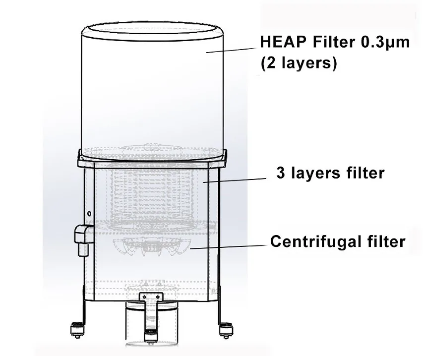
A centrifugal oil mist collector draws contaminated air from an enclosed machine tool, separates coalesced oil droplets and filters the smaller remaining mist before returning air to the workshop.
1. Capture air from the machine enclosure
The collector is connected to the CNC machine enclosure through an inlet and duct or mounting interface. Airflow creates negative pressure that draws oil and coolant mist away from the machining area and into the collector.
2. Use centrifugal force to coalesce droplets
Inside the collector, a rotating turbine produces centrifugal force. Suspended oil droplets are driven together, forming larger droplets that are easier to separate from the airflow.
3. Capture smaller remaining particles
After the centrifugal stage, air passes through a multilayer filter. This stage captures smaller pollutant particles that remain in the airflow. Filter condition should be checked according to the coolant, particulate load and operating cycle.
4. Add optional post-filtration when required
For applications involving micromist, smoke or vapor, the supplied TINME specification describes an optional HEPA post-filter. The stated performance is up to 99.97% at 0.3 micrometers with this optional filter. The source document does not state an H13 classification.
5. Drain separated liquid
Coalesced liquid moves to the drainage path and can be returned to the process where the coolant system and site procedures allow. Drainage routing should prevent restrictions, backflow and leakage.
Where centrifugal collectors are used
Typical enclosed equipment includes CNC lathes, Swiss-type lathes, machining centers, grinding machines, gear hobbing machines and circular saws. Final collector selection depends on the enclosure, process, coolant, mist load and available power supply.
Discuss Your CNC Oil Mist Application
Send the machine type, enclosure size, coolant, operating conditions and available power supply for model-selection support.
Request Application Advice